Trellisign Electromagnetic Solutions
Comprehensive Electromagnetic Solutions
Comprehensive Electromagnetic Solutions
1. Impedance Matching
Antennas have a characteristic impedance that can change with frequency. For efficient power transfer, the antenna's impedance must match the transmission line (usually 50 or 75 ohms). If there is a mismatch, some of the signal gets reflected instead of being transmitted, reducing efficiency and potentially harming the transmitter.
2. Size and Weight Considerations
In portable devices and specific applications, the size and weight of the antenna are important factors. A bulky or heavy antenna may not be practical.

The range of frequencies a signal can use.
The orientation of the electric field radiated by the antenna.
The extent to which the antenna focuses radiation in a specific direction.
The size constraints for fitting the antenna in a given area.
The amount of power transmitted in the direction of maximum radiation.
The ratio of the power radiated by the antenna to the power supplied to it.
Essential for mobile and fixed communications, enabling voice and data transmission over various distances.
Critical for radar systems in detecting and tracking objects, enhancing safety and navigation.
Facilitates accurate positioning and navigation for vehicles and personal devices.
Enables data collection from remote locations, enhancing IoT applications across various sectors.
Utilized in medical devices for wireless communication and monitoring of patient health.
Supports vehicle-to-vehicle and vehicle-to-infrastructure communication for enhanced safety.
Crucial for communication and navigation systems in aircraft and spacecraft.
Essential for secure communication, surveillance, and navigation in defense systems.
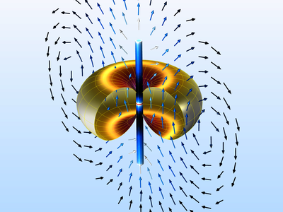
A dipole antenna is a basic radio antenna made up of two symmetrical conductive elements, such as wires or rods. It is designed to transmit and receive radio waves, with its length typically matching the wavelength of the signals it processes. The feedline is connected at the center, where the electrical signal is applied or received. Dipole antennas are popular because they are simple, efficient, and widely used in wireless communication. They also serve as the foundation for many advanced antenna designs.
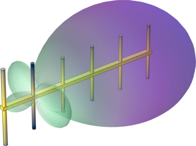
The Yagi-Uda antenna is a directional antenna commonly used for radio and TV reception. It consists of a driven element, a reflector, and multiple directors, all aligned on a boom. The reflector boosts signal strength by blocking interference from behind, while the directors focus the signal forward, increasing gain. This design helps the antenna transmit or receive signals in a specific direction, making it a simple and effective solution that has been used for many years.

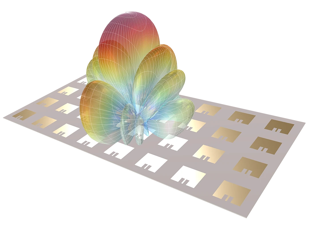
A microstrip patch antenna is a compact, low-profile antenna made by etching a radiating patch onto a dielectric substrate, with a ground plane on the other side. The size of the patch determines its resonant frequency, making it useful for various wireless applications. It is easy to manufacture, cost-effective, and integrates well with planar circuits. However, it typically has a narrow bandwidth and lower gain compared to other antennas. Due to its compact size and easy integration, it is widely used in devices like mobile phones and GPS receivers.
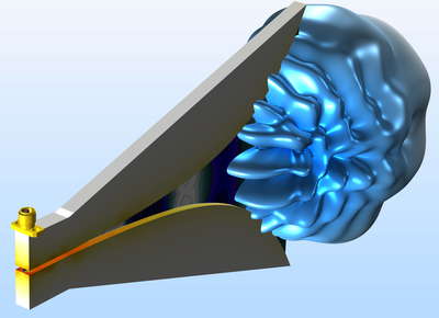
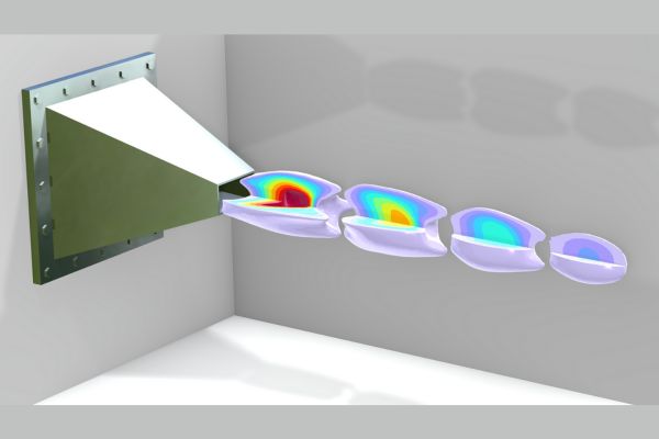
A horn antenna is a flared waveguide that efficiently focuses radio waves into a directed beam. It is commonly used for microwave frequencies, providing high gain and minimal signal loss. These antennas are often used as feed horns for larger systems like satellite dishes and radar. Their design reduces reflections and supports broadband operation. Horn antennas are popular due to their simple structure and reliable performance across various applications.
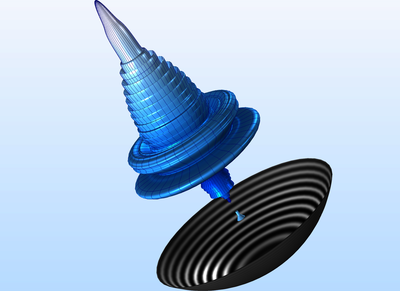
A parabolic antenna features a curved, dish-shaped reflector that focuses radio waves, allowing it to receive signals from a specific direction or transmit them in a narrow beam. It is commonly used in satellite communication, microwave relays, and radar systems. The parabolic shape directs radio waves to a focal point, improving signal strength. This design provides high gain and strong directionality, making it ideal for long-distance communication.
RF circuits are highly sensitive to noise from various sources (thermal noise, power supply noise, external interference).
Integrating antennas effectively with RF circuits while maintaining performance.

Understanding electromagnetic fields, wave propagation, and transmission lines forms the foundation of RF design.
RF circuits require precise designs using components like inductors, capacitors, and transistors to operate effectively at high frequencies.
Choosing the right components, such as filters, amplifiers, and matching networks, is critical to achieving optimal system performance.
Properly matching impedance between components and transmission lines reduces signal reflections and ensures maximum power transfer.
Reducing noise in RF circuits is vital, especially for sensitive receivers, as it ensures weak signals are not lost or distorted.
Maintaining amplifier linearity is crucial for preserving signal integrity and avoiding unwanted distortion in transmitted and received signals.
Efficient power handling ensures stability and performance, especially in high-power applications like base stations or radars.
Seamlessly connecting RF systems with antennas ensures optimal signal transmission and reception.
Enables mobile phones, Wi-Fi, and Bluetooth technologies for seamless connectivity.
Used in air traffic control, weather monitoring, and military applications for detecting and tracking objects.
Essential in MRI and ultrasound technologies for non-invasive diagnostics and imaging.
Utilized in vehicle communication systems, radar for collision avoidance, and keyless entry systems.
Supports automation, remote monitoring, and control systems in manufacturing processes.
Facilitates smart meters, connected devices, and urban infrastructure management.
Critical for secure communications, surveillance systems, and electronic warfare.
Signal Integrity (SI) refers to maintaining the quality of an electrical signal as it travels from its source to its destination. It ensures that the signal's shape, timing, and strength remain intact throughout the transmission path.
Signals can lose strength as they travel through transmission lines, especially over long distances or at high frequencies.
Signals can become distorted due to various factors like impedance mismatches, reflections, and losses. This distortion can alter the signal's shape, amplitude, and timing, making it difficult for the receiver to interpret the data correctly.
Ensures reliable data transmission and minimizes errors in high-speed digital systems.
Critical for the performance of advanced driver-assistance systems and in-vehicle communication.
Ensures signal integrity in communication and navigation systems used in aircraft and military applications.
Supports the performance of sensors and control systems in manufacturing and process automation.
Power Integrity deals with the quality of the power delivered to the components in an electronic system. It focuses on ensuring that all components receive clean and stable power.
Power integrity issues can contribute to EMI, which can cause interference with other electronic devices
Fluctuations in the power supply voltage can cause circuits to malfunction or produce incorrect results. This can be due to excessive voltage drop, ground bounce, or power supply noise.

Ensures reliable data transmission and minimizes errors in high-speed digital systems.
Critical for the performance of advanced driver-assistance systems and in-vehicle communication.
Ensures signal integrity in communication and navigation systems used in aircraft and military applications.
Vital for the accuracy and reliability of data in medical imaging and monitoring equipment.
